
HOW TO SIZE VENTURI STEAM TRAP?
Among the factors affecting the efficiency and reliability of a steam trap operation, proper steam trap sizing holds great importance. An incorrectly sized steam trap, mechanical or venturi, will result in either condensate backup or steam losses regardless of its operational working design. Steam trap sizing doesn’t refer to the selection of its connection size to match steam pipe size; instead, it means the appropriate sizing of the internal orifice which, for SMART Steam Trap technology, is venturi insert through which the condensate discharge takes place. For systems using low steam pressure, the connection size of the steam trap is in accordance with the capacity of orifice size, whereas steam traps used in industries for process applications require it to properly size orifice. Condensate capacity that can get through DN50 steam trap can be the same as that of size DN15 steam trap if they have the same size orifice. It is misleading to think that a larger body will discharge a larger amount of condensate. The size of steam piping and connection to the steam trap is selected after determining the condensate capacity, and its internal orifice discharge capacity. Moreover, condensate capacity is independent of the pipe connection or steam trap connection size.
To determine the correct orifice size for the Venturi steam trap, the following information should be obtained:
- Maximum steam pressure (to define steam trap body rating)
- Maximum steam temperature (to define steam trap body rating) – Operating pressure (barg)
- Steam pressure before steam trap inlet (barg)
- Steam pressure before steam trap inlet (barg)
- Condensate return line pressure after the steam trap outlet (barg)
- Maximum condensate capacity (kg/hr)
- Nominal condensate capacity (kg/hr)
- Minimum condensate capacity (kg/hr) is helpful but is not the main requirement
- For process application steam trap sizing, we need to know if the process is continuous or in batch to understand how condensate will form and flow through the trap station
To start, we look first at the maximum numbers to understand if the proposed steam trap design will withstand those conditions. The same applies to orifice selection; even though most process applications work the majority of the time at nominal capacity which can be anywhere between 10% to 50% below maximum capacity, we still need to take into account the orifice size for the maximum load conditions. A correctly selected steam trap should be able to withstand maximum steam pressure, temperature, and maximum condensate load without affecting manufacturing process performance.
So, it then brings the question of where and how to get this information?
To start gathering this information, it is good to have a sheet where you can write down the necessary sizing information. For this purpose, SMART Valves sizing sheets have been implemented that can be requested by the client. When we look at the steam system to propose a new product, we need to identify the maximum steam pressure of the system to determine the required product specs. A good start is to look for this information by asking the team working in the boiler room and look in system specification or at safety valves that are installed in the steam system for overpressure protection.
Secondly, we need to know the operating steam pressure which is usually determined through steam pressure gauges installed in the steam system. If there is none, the other option is to see what is the pressure generated by the steam boiler, and then based on system design and distance between boiler room and steam trap, the steam pressure drop can be estimated from steam traveling through pipes. In this way, we can arrive at the pressure number that can be used for sizing the steam trap. An even better option is to install a brand new pressure gauge in the system. A pressure gauge not only helps to size the steam trap by giving feedback on steam pressure, but it can also be used to check if the system is working properly and the newly installed steam trap is working optimally. Next, we need to determine condensate return pressure. It is easy to account for any trap that is discharging condensate on the ground as it makes them atmospheric and the pressure is 0 BARG. Also, if there is a pressurized condensate return system due to the design, it maintains specific pressure in the condensate lines to work. This system has pressure gauges installed to control the required setpoints which makes the system pressure easily identifiable.
However, most condensate return systems are vented and will have back pressures above atmospheric pressure at the discharge side of the steam trap caused by the condensate return system design or the operation of the steam and condensate return system.
The factors that will affect this pressure are piping distance and rises in system pressurization due to lack of steam trap maintenance and letting failed open and leaking steam traps pass live steam in condensate system which pressurizes the system over time, thereby increasing the system pressure.
Also, it is necessary sometimes to lift condensate from a steam trap to a higher-level condensate return line which will generate backpressure. A rule of thumb is that for every 1-meter condensate return pipe lift, it generates ≅ 0.1 barg of backpressure. This is important to account for as there can be sometimes up to a 5-meter condensate pipe lift, which will generate 0.5 barg of backpressure.
The main reason why it is important to know the pressure before and after the steam trap is to calculate the pressure differential for the given steam trap location. The difference between a trap’s inlet pressure and backpressure is called the ‘differential pressure’, which is a factor affecting how much condensate can be discharged through the fixed orifice. It is important to note that all traps have fixed orifice. Even after 30 years of venturi technology being available in the market and growing year over year, there are engineers who have been taught in seminars or by sales reps from competing companies that only Venturi-type traps have a fixed orifice, therefore it cannot work on variable conditions. This is totally incorrect and I would say that almost the opposite is true.
After the steam trap is installed, no matter what style or brand, the orifice in that trap will be fixed. However, the thing which differentiates the SMART Steam Trap design is that it has a replaceable venturi insert that serves as an orifice. This product option comes in very handy when you can potentially use the same trap for 20 years, and if the steam system design has changed over time where steam trap orifice needed more capacity. With SMART Steam Trap, you can exchange it by just replacing the venturi insert. So we do have a changeable orifice design, but you still need to stop the steam trap to replace it.
Going back to the required information for sizing, once pressure differential is known, the remaining factor that we need to know to select orifice is condensate loads. Condensate load amount will greatly differ between distribution steam trap loads and process steam trap loads. Distribution steam traps generally will have a small amount of condensate to handle when the system is operating at full capacity and, therefore, are also not looked after very often or are implemented with incorrect capacity in the first place. Very often, one may be faced with a situation where precise data regarding the condensate loads in distribution lines may not be available. In such situations, the condensate loads can be approximately estimated.
This is a sample table that can be used to estimate loads and one of the benefits from working with SMART Steam Trap Technology is that each of their traps sold worldwide comes with the engineering support required to get it working optimally. A client who does not know their distribution line loads can just call the company and get a simple to follow form to fill out with information about steam pipe size, insulation thickness, and the approximate distance between traps from which our in-house engineer makes all necessary calculations to get condensate load for the ordered units.

Then, there is the most important steam trap group known as “process steam trap”. Process steam trap is a steam trap that is located right after the steam user, where steam is pushed for the heat exchange process. It can be reboiler, heat exchanger, dying machine, cooker, sterilizer, destination column, and process where steam is used as energy for heat transfer purpose.
If these traps are not performing well, then it may impact product quality. This is the reason why this steam trap group is the most often looked after. If they fail, and the mechanical type traps can fail often, the maintenance team will need to replace them or fix them on short notice.
To size the process trap, it is essential to know the accurate condensate loads to make the new steam trap work without mistakes on the first try. In larger organizations with dedicated engineering teams working to support the factory, the usual way to get information about condensate loads is to request them from process engineers who are responsible for unit reliability in that facility. They usually have a good understanding of steam and condensate loads and will provide this information. For those cases where they do not know condensate load, they probably know the steam flow rate going specifically to the process with the steam trap. This steam flowrate amount can be used to determine condensate load as the steam flow rate will be equal in amount to the condensate load once heat transfer takes place.
For example, if we have a heat exchanger and we know the maximum steam flow rate is 1000 kg/hr and the nominal flow rate is 800 kg/hr, it will generate 1000 kg/hr condensate at max load and 800 kg/hr condensate at nominal load.
Once we know Pressure differential and condensate load, the rest is to add a safety factor and we get a capacity number that can be used to select the orifice. Since mechanical steam traps are built with something moving inside that either cycles on and off or modulates, mechanical steam trap manufactures can sometimes suggest a safety factor of up to 3 to 1 to handle cold start load and maximum loads efficiently.
The SMART Steam Trap, which works on the constant discharge principle, never holds back condensate and discharges it as it forms, thereby improving condensate discharge rate and not requiring to oversize the orifice 3 times.
In an average venturi trap, a safety factor for process applications is 1.5 to 1 for addressing all the conditions such as cold startup, maximum load, nominal, and the minimum; for distribution and trace heating steam traps, it is around 2 to 1.
Once we know the information, our engineer inputs this information in our technical calculator and we get a precise orifice required for the process steam trap.
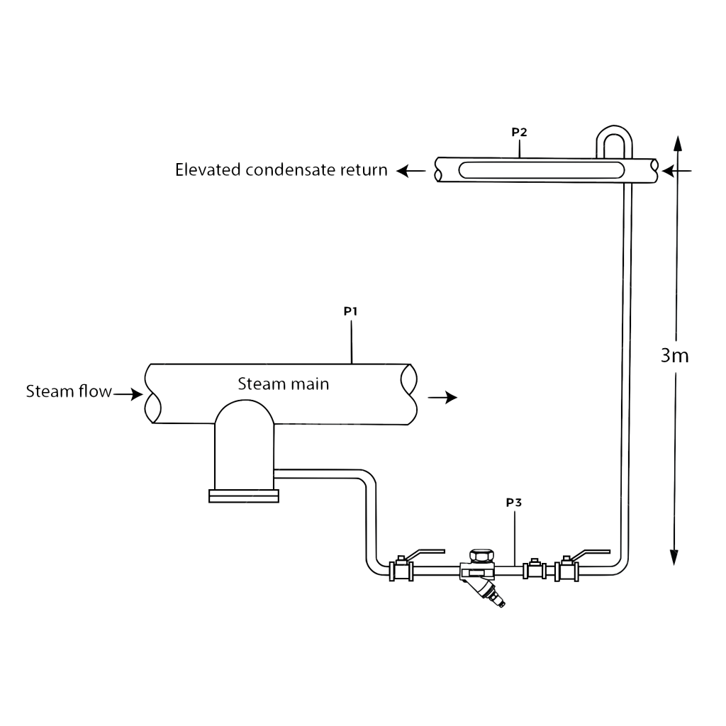
Now, let’s look at some real-life examples: 1. Steam distribution trap (drip leg). This is a trap that is fairly easy to size and, if implemented incorrectly, cannot make a big enough problem to affect manufacturing. To start, we usually ask the largest and smallest pipe diameter in the system, approximately how long is main distribution line, what is steam pressure, if they know how thick is insulation and how far apart are drip leg stations. Once we have that information, we run a calculation for traps where they have the most condensate in main lines and find capacity for that steam trap. • P1 Steam line pressure = 5 (barg) • P2 Condensate line pressure = 0.2 (barg) • P3 Pressure at steam trap outlet = 0.5 (barg). Rise in condensate piping after the steam trap (distance 3 m) = 0.3 (barg) plus P2 0.2 (barg) = 0.5 (barg) – Steam mainline 250 mm, it is insulated and located outside – Distance between steam trap stations = 25 meters

By inputting data in our formula, we estimate that there is 13 kg/hr condensate

When we take the capacity of 13 kg/hr and add a safety factor of 2 for the distribution trap, we end up with a required load of 26 kg/hr. Based on that capacity, we selected our standard capacity orifice S and average it out to all traps in this pressure category. Then after each steam trap is installed and commissioned, if any of the steam traps need to be resized, it is done by replacing an orifice insert inside that specific trap without the need to replace a whole steam trap. Sizing one distribution trap in a place where there is a large condensate load and then selecting the same orifices for all traps in that pressure category is a very effective way to size large groups of traps and save management time. If there is a steam distribution system with thousand steam traps in it, it would be very labor intense and inefficient to gather information for each steam trap. It is better to identify where the largest load necessary to handle is and then take it and average it out to the rest of the units.
Once the trap is delivered, the great thing about Venturi type steam traps is that they come with a very long warranty from most venturi style steam trap manufacturers these days. The SMART Steam Trap comes with 20 years of guaranteed performance against steam leaks and failed ones and commissioning inspection for each unit sold. The inspection is done by measuring temperature before and after the steam trap and comparing it with what it is supposed to be. If any trap is not performing well, it is scheduled to be resized immediately. The warranty term will not start for any trap without it being commissioned; therefore, our clients can have peace of mind that if they acquire SMART Steam Trap, they will get performance feedback to be sure that all new steam traps work optimally. The commissioning is usually done either by the client himself by following instructions or by one of our sales agents.
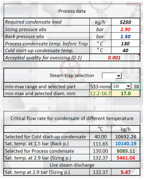
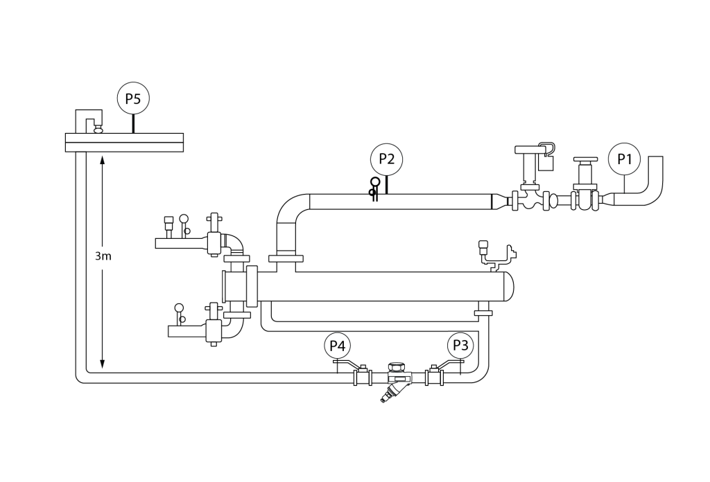
Now, let’s look at the sizing process steam trap on the heat exchanger application. As described before, to size process steam trap, more information is needed and conditions cannot be averaged since one orifice will not fit for all applications unless they are all identical. What we will look at is a heat exchanger for water tank application. The process is to maintain water in the tank at 60⁰C and, at some intervals, this water is used up and then filled back again for heating to 60⁰C. By adding all the numbers, the total condensate load of this steam trap must be able to handle the capacity of 3500 × 1.5 = 5,250 kg/hr, which at 1.4 (barg) pressure differential will require to use an S38 insert .
Steam system conditions:
Steam line pressure = 2.5 barg
Heat Exchanger steam flow requirement = 3500 kr/hr.
1. Delivery pressure to the exchanger = 2.5 barg
• P1 = 2.5 barg
2. Pressure Drop across the control valve = 0.5 barg
• P2 = 2.5 –0.5 = 2 barg
3. Pressure Drop in the heat exchanger = 0.1 barg
• P3 = 2-0.1=1.9 barg
• P3 = Inlet Pressure to the steam trap station
4. Backpressure in the condensate line = 0.2 barg
• P5 = 0.2 barg
5. Rise in condensate piping after the steam trap (distance 3m) = 0.3 barg, 0.1 barg for each meter rise
• P4 = 0.5 barg = 0.3 barg for the rise in the condensate piping and 0.2 barg pressure at P5
6. Steam trap differential pressure = P3 (1.9 barg) – P4 (0.5 barg) = 1.4 barg (differential pressure)
7. Steam trap selection:
• Based on the condition of intake, we need to select SMART Steam Trap STC DN50 BSP S38 Insert
• Steam trap orifice for this capacity is 17 mm large
• Steam trap sizing factor = 1.5 to 1
• Capacity 3500 × 1.5 = 5,250 kg/hr
• The steam trap station must have the capacity to flow 5,250 kg/hr hour with a 1.4 barg differential pressure.
Conclusion: In conclusion, experience in system engineering and different pieces of equipment is needed for proper steam trap sizing. There are times when experience dictates selecting a larger size orifice than what a calculator may tell you. The outcomes depend on the quality of data and the client’s openness to work with, giving accurate feedback. The biggest advantage for working with SMART Steam Trap technology is that it combines the use of venturi technology to completely take out any moving mechanisms that can fail in a steam trap, provides an orifice design that is replaceable with larger or smaller capacity, and the company policy to verify each delivered steam trap performance through dedicated partners around the world. Additionally, we do not leave any trap that is not optimally sized in the client’s system without readjusting it. Working with SMART Valve customer service does not end after-sales are done, it only starts from there and continues for the next 20 years.
So, start by thinking about making a trial with SMART Steam Traps, and then gather the following data:
- Maximum steam pressure
- Design pressure
- Return line pressure
- Condensation rate of equipment
- Startup time and load
- Locate some currently failed open or leaking steam traps that you need to replace
Once the information is obtained, just reach out to our sales office and we will be glad to set your company for success with the SMART Steam Trap 90-day trial.
Related articles

Let’s discuss your needs