
VENTURI INSERT WORKING STAGES
2021-03-18
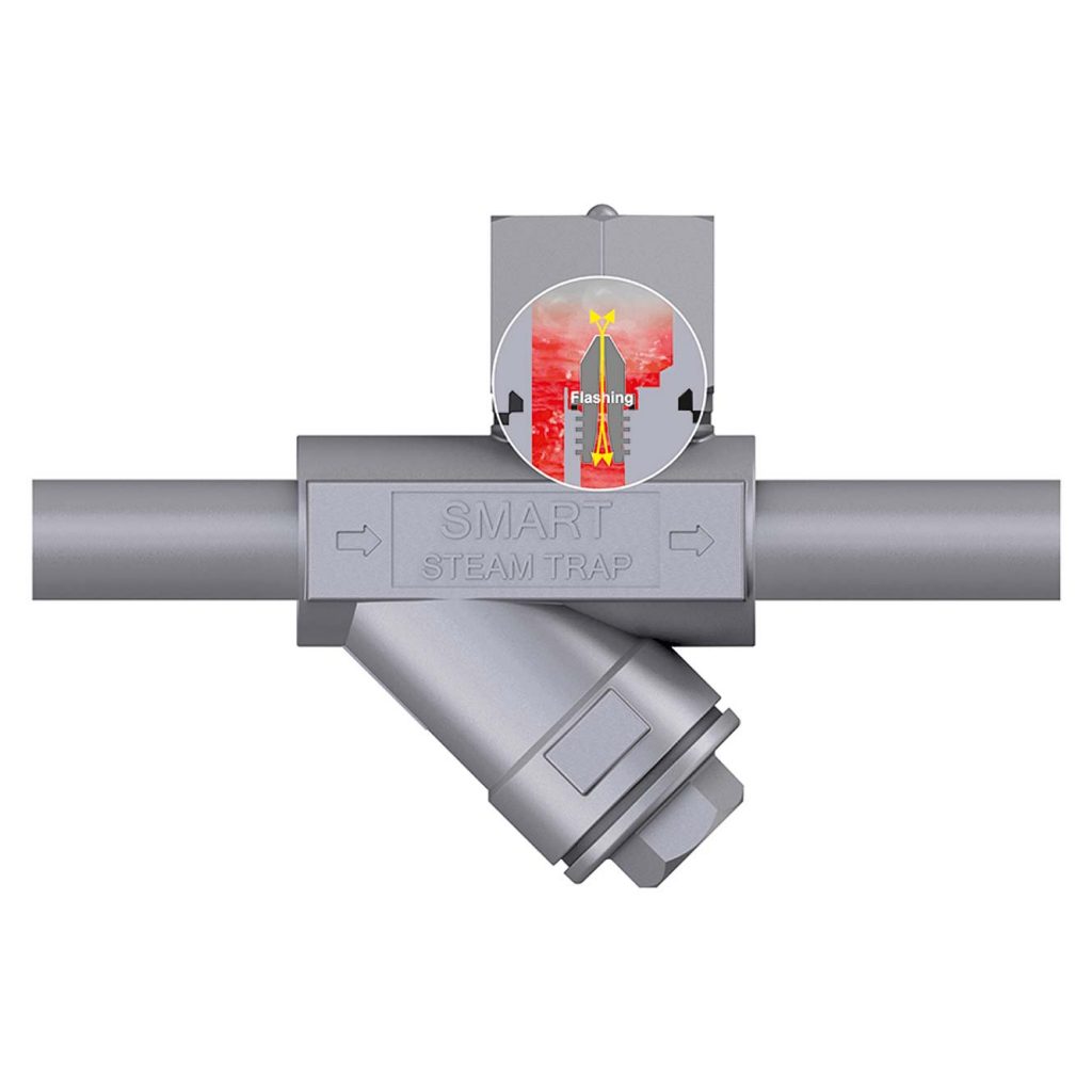
The capacity of our SMART Steam Traps, which are Venturi Style Traps, is a function of the insert channel diameter and the dimensions of the Venturi nozzle section. By utilizing the natural laws of physics as well as the change in the amount of flash steam with the change in pressure, the capacity of the SMART Steam Trap can adjust with the changes in process conditions. All condensate removal valves of SMART Steam Traps utilize an optimally sized venturi nozzle to separate the steam from the condensate.
- The density of condensate is about 1,000 times greater than that of steam.
- From the basic physics of a two-phase flow, we know that the heavier condensate phase will preferentially pass through the nozzle as compared to the lower density steam.
- In a saturated steam system, a steam and condensate mixture are always present.
- While condensate loads commonly go from max to low, there is always enough condensate to create a seal at the inlet of the venturi nozzle that holds back the live steam. However, the condensate is discharged preferentially and continuously through the nozzle.
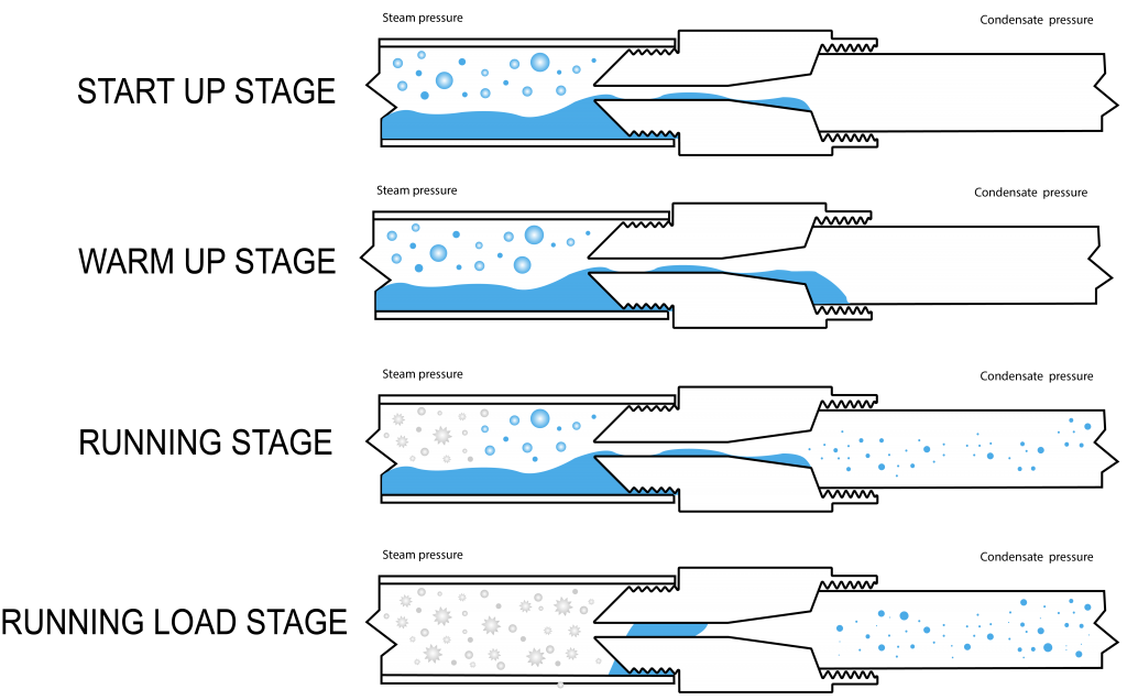
- For varying load applications, the regulation of the capacity in a venturi nozzleis achieved by the two-phase flow with the first being the continuous discharge of condensate without flashing condensate. This phase occurs when there is maximum condensate load and when the venturi nozzle inside is filed with 100% condensate. Hence, there will be no room for live steam to pass through as the condensate amount will act as a plug at stage 1 flow to block the live steam.
- Once the flow of condensate drops below 90% of its maximum available space inside the venturi nozzle, then it opens room for condensate to flash and expand. This is considered the 2nd phase of flow where partial condensate is flashed by the pressure drop in the venturi nozzle section.
- As the pressure of the condensate that is discharged through the venturi nozzle is reduced, it contains less energy. However, since energy cannot be destroyed, the difference causes some of the condensate to be converted into “flash” steam.
- Depending on pressure differential conditions, and space inside in venturi nozzle enough for flash steam to expand, the portion of condensate going into the venturi nozzle now will be flashed. This will fill the space not covered by condensate by expanding multiple times above the volume of condensate. As a result, backpressure will be created inside the nozzle that will make it impossible for live steam to pass through, but condensate being 150 times heavier than live steam will have enough force to overcome this back pressure and keep draining continuously from the steam trap.
- Flash steam is formed in the Venturi nozzle due to the pressure drop in the venturi nozzle tube. The amount of flash steam is defined by pressure in the upstream and downstream side of the venturi nozzle and condensate load relative to the maximum space available for flash steam to expand inside in venturi nozzle.
- The flash steam generated backpressure is caused by flash steam staying inside the venturi nozzle due to the length and diameter of the venturi nozzle channel which is long and wide enough to keep enough flash steam generated from a portion of condensate discharged continuously. Because the flash steam generated backpressure is contained inside the venturi nozzle at any time during the 2nd phase of flow, it generates a reliable plug that is strong enough to stop lower density elements, such as live steam, from passing the venturi nozzle through maximum to minimum condensate load variations when venturi nozzle size is selected optimally for maximum condensate loads.
Related articles
SMART STEAM TRAP SELECTION GUIDELINES
When we size the trap, we group all SMART Steam Traps in the plant under one of these categories...
Read more

Let’s discuss your needs